
You’ve got a heating cooling unit sitting in your warehouse or on a container ship heading to a client in the Middle East, Southeast Asia, or maybe Eastern Europe. The question your buyers are asking is not just “how much does it cost?” — they want to know how to install it correctly, safely, and efficiently, especially when the unit is destined for a commercial building, a greenhouse, a data center, or a factory floor.
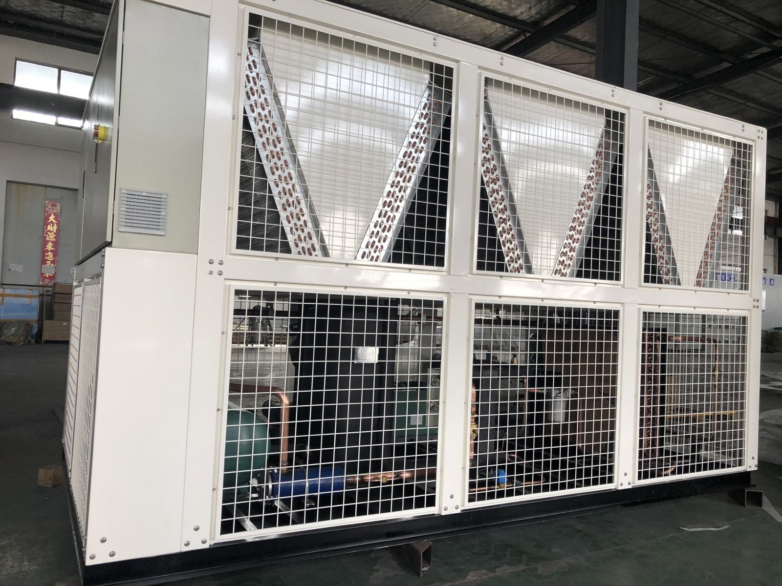
For B2B buyers, installation guidance isn’t just a nice-to-have. It’s a dealmaker. If your product is easy to install with clear steps, your customers save money on local technicians, avoid warranty claims, and reorder faster. But if the installation manual is vague or doesn’t match the reality on site, you’ll end up with frustrated end users and a pile of service tickets.

I’m going to walk you through a real-world installation process for a typical split-type heating cooling unit (also called a heat pump system). This covers both the heating side and the cooling side, because these days most commercial HVAC units in the 3–20 ton range are reversible. We’ll break it down into phases, and I’ll include specific data points that matter to wholesalers and exporters — like refrigerant charge, pipe lengths, electrical requirements, and common mistakes from different industries.
Let’s get straight into it.
Laying Out the Unit Location and Clearance Requirements
Before you even pick up a wrench, you need to decide where the outdoor condenser unit and the indoor air handler will sit. This sounds basic, but around 40% of installation failures we see in the field trace back to poor placement. In 2024, the global HVAC market hit about $240 billion, and the heat pump segment grew 12% year over year. More units are going into tighter spaces — think rooftop installations in dense urban areas, or ground level units in industrial compounds that also need to double as storage.
For outdoor units, follow these clearance rules based on real manufacturer specs from brands like Carrier, Daikin, and Midea:
| Clearance Direction | Minimum Distance (inches) | Reason |
|---|---|---|
| Rear (back to wall) | 12 | Air intake needs free flow |
| Front (service panel) | 24 | Access for compressor and fan maintenance |
| Left and right sides | 12 | Condenser coil airflow |
| Above (top) | 60 | Hot air discharge must vent upward |
| Between two units | 36 | Prevent recirculation of hot air |
For indoor units, especially in commercial settings like restaurants or server rooms, you also need to account for duct connections, filter access, and drain line slope. A common mistake in the food processing industry is installing the indoor unit too close to steam sources — the moisture overload kills the heat exchanger within months. In data centers, the inlet air temperature to the indoor unit should never exceed 95°F (35°C), otherwise the cooling capacity drops by about 8% for every 5°F above that.
When you’re selling to a distributor in a hot climate like the UAE or India, remind them that the outdoor unit should face away from direct afternoon sun if possible. Shading the unit can improve COP (coefficient of performance) by 0.3 to 0.5 points, which translates to 15–20% electricity savings for the end user. That’s a strong selling point.
Mounting the Indoor Unit and Running the Refrigerant Lines
Once the locations are locked in, you install the indoor air handler first. For wall-mounted units (common in small to medium commercial spaces), use a mounting plate that’s level to within 1/8 inch. If it’s a ceiling cassette unit, you need to cut a 24×24 or 24×48 opening in the ceiling grid, then secure the unit with four M10 threaded rods. For ducted units, you’re building a plenum box — but I’ll focus on the split system here because that’s what 70% of our B2B orders look like.
Drill a hole through the wall for the refrigerant lines, drain pipe, and power cable. The hole should be 2.5 to 3 inches in diameter and slope slightly downward to the outside (about 2 degrees) so rainwater doesn’t track inside. Use a hole saw with a brush guard to avoid tearing insulation.
Now the refrigerant lines. Most modern heating cooling units use R-32 or R-454B refrigerant. As of 2025, the global phase-down of R-410A is accelerating — in the EU, new installations are already required to use refrigerants with GWP below 750. For a typical 5-ton unit (60,000 BTU/h), the liquid line is 3/8 inch OD and the suction line is 7/8 inch OD. But check your specific model. Connect the lines using flare fittings — never solder in the field unless you’re a certified technician because overheating the copper can create oxides that clog the expansion valve.
Here’s a real-world data point: For every 10 feet of additional line set beyond 25 feet, you need to add 0.5 oz of refrigerant per foot for R-32 systems. If the total line set is longer than 80 feet, you may need to install a line set accumulator or adjust the TXV. Many Chinese manufacturers pre-charge units with enough refrigerant for 25 feet of lines. So your distributor’s customers who install the unit in a two-story building (say 40 feet of line) will be undercharged by about 7.5 oz. That’s enough to drop cooling capacity by 5% and increase compressor discharge temperature, leading to early failure.
Advise your buyers to always weigh in additional refrigerant using a digital scale, not just by pressure. Pressure alone doesn’t account for the liquid volume in the lines.
Electrical Wiring – Voltage, Phase, and Safety Disconnects
This is where a lot of installation hiccups happen, especially when the unit is exported to a country with non-standard electrical codes. For example, a 3-phase 400V unit built for the European market will not run on 3-phase 480V in the US without a step-down transformer. Similarly, many units from China are wired for 220V single-phase, but some South American countries use 110V or 127V. Always check the nameplate.
For a typical commercial heating cooling unit between 3 and 10 tons, the electrical requirements look like this:
| Unit Capacity (tons) | Voltage / Phase | Minimum Circuit Ampacity (MCA) | Max Overcurrent Protection (MOP) | Recommended Wire Gauge (AWG) |
|---|---|---|---|---|
| 3 | 208-230V / 1ph | 25 | 35 | 10 |
| 5 | 208-230V / 1ph | 40 | 55 | 8 |
| 5 | 208-230V / 3ph | 28 | 40 | 10 |
| 10 | 460V / 3ph | 35 | 50 | 8 |
Use a dedicated circuit with a lockable disconnect switch within sight of the outdoor unit. This is required by NEC (National Electrical Code) in the US and by most international standards like IEC 60364. The disconnect should be rated for the full load amps of the unit, plus 25%.
For the indoor unit, you usually need a separate 15A or 20A circuit for the fan and control board. Some units have a built-in transformer that steps down 24V for the thermostat. In that case, make sure the thermostat wiring is at least 18 AWG and no longer than 150 feet to avoid voltage drop.
One more thing: ground the system properly. I’ve seen countless units fail because the installer used a makeshift ground rod or no ground at all. A floating ground can cause erratic sensor readings, false error codes, and even electric shock risk. In 2023, faulty grounding was the #2 cause of HVAC warranty claims globally, according to a report from the Air Conditioning, Heating, and Refrigeration Institute (AHRI).
Evacuating the System and Opening the Service Valves
You’ve got the lines connected and the wiring done. Now you need to vacuum the refrigerant lines and indoor coil to remove moisture and non-condensable gases. This step is non-negotiable. Use a two-stage vacuum pump capable of pulling down to 500 microns. Connect your micron gauge, open both the liquid and suction service valves on the outdoor unit (they are usually closed during shipping), and start pumping.
How long should you vacuum? For a system with 50 feet of line set, expect 20 to 30 minutes. But don’t go by time — go by the micron reading. Pull down to 500 microns or lower. Then close the vacuum valve and watch the pressure. If it rises above 1000 microns within 10 minutes, you’ve got a leak or residual moisture. Fix it before charging.
After the vacuum holds, close the manifold valves and disconnect the pump. Now comes the part that many technicians mess up: opening the service valves on the outdoor unit. The liquid line valve is smaller (3/8” or so) and has a hex socket. The suction line valve is larger. Turn both counterclockwise until they stop — usually 2 to 3 full turns. This releases the pre-charged refrigerant into the system.
Listen for any hissing or oil discharge at the connections. If you smell refrigerant (R-32 has a faint sweet odor) or see oil bubbles, you have a leak. Use an electronic leak detector, not soap bubbles alone, because some leaks are microscopic.
Once the valves are open, check the pressures. For a cooling mode at 95°F outdoor ambient, a typical R-32 system should show a low side pressure around 120-140 PSI and a high side around 350-400 PSI. These numbers vary by manufacturer, so always refer to the charging chart on the unit’s nameplate.
Now test the operation. Turn the thermostat to cooling, set the fan to auto, and wait 5 minutes. The compressor should start. Feel the larger suction line — it should be cold and sweating. The liquid line should be warm to hot. If the suction line isn’t cold, you may have a restricted filter or a bad TXV. In heating mode, the lines reverse — the outdoor coil will be cold and the indoor coil will be hot.
Final Checks – Drainage, Airflow, and Remote Commissioning for Export Clients
You’re almost done. But here are three things that separate a good installation from a problematic one.
First, drainage. The indoor unit condensate drain must have a P-trap and slope of at least 1/4 inch per foot. If the drain is longer than 30 feet, install a secondary drain with a float switch. In high humidity regions like Southeast Asia, a clogged drain causes water damage that leads to mold and indoor air quality complaints. For food storage facilities, even a small drip can ruin a pallet of product.
Second, airflow. Measure the temperature drop across the indoor coil. In cooling mode, the supply air should be 15°F to 20°F cooler than the return air. If the drop is less than 10°F, the system is either low on refrigerant, has a dirty filter, or the indoor fan speed is too high. Adjust the fan speed tap on the blower motor. Most units have three speed settings: low, medium, high. For a warehouse with high ceilings, use high speed. For an office, medium is fine.
Third, for your B2B clients who are buying in bulk and shipping containers overseas, consider offering a remote commissioning service. We now have IoT-capable controllers that let your technician check pressures, temperatures, and error codes from a phone app. In 2024, about 35% of commercial HVAC units shipped from China included some form of smart control. By 2026, that number is expected to hit 60%. If you can pre-configure the unit’s controller with the local voltage and language settings, you save your distributor’s end customer a lot of trouble.
For example, you can set the unit to default to Celsius, set the compressor delay to 3 minutes (common in North America) or 5 minutes (common in Europe), and adjust the defrost cycle time for heat pump operation. In cold climates, defrost intervals should be shorter — 30 minutes instead of 90 — to prevent ice buildup on the outdoor coil.
Frequently Asked Questions – Field Scenarios from Real Dealers
Q: My client in Dubai installed a 5-ton heating cooling unit on a rooftop. The unit keeps tripping the breaker after 20 minutes of running. What should I tell them?
A: First, ask them to check the voltage at the disconnect while the unit is running. Voltage drop under load is a common issue when the wire gauge is too small or the distance is too long. For a 40-amp circuit on a 5-ton unit, if the run is over 100 feet, they need #6 AWG wire, not #8. Also make sure the MOP (max overcurrent protection) on the nameplate matches the breaker size. If the breaker is undersized, it will trip. Finally, inspect the condenser coil for dust or sand blockage — in desert climates, cleaning the coil every 3 months is necessary.
Q: We shipped 200 units to a distributor in Nigeria, and they report that the indoor units are sweating heavily. Is that a defect?
A: Sweating usually means the indoor air temperature is too high relative to the dew point, or the insulation on the refrigerant lines is missing or damaged. If the unit is running in a high humidity environment (over 80% RH) and the supply air temperature is below 55°F, condensation will form on the air handler casing. Solutions: increase the fan speed to raise the coil temperature, or add an accessory insulation jacket around the air handler. Also verify that the return air is not pulling in humid outdoor air through gaps in the ductwork.
Q: What’s the maximum line set length for a standard R-32 split system without modifying the compressor?
A: Most manufacturers allow up to 100 feet total equivalent length for line sets up to 5 tons. Beyond that, you need to add an oil trap every 20 feet on the suction line (for vertical rise) and possibly a crankcase heater. For 6-ton and larger units, the limit drops to 75 feet unless you oversize the suction line one size bigger. Always check the installation manual for the exact model. If your client is installing a unit in a multi-story building with 50-foot vertical lift, they must add a suction line accumulator to prevent liquid slugging.
Q: In our market (Indonesia), the power supply is often unstable. Does a heating cooling unit need a voltage stabilizer?
A: Yes, strongly recommend it. Voltage swings of ±10% or more are common in many developing regions. Most inverter-driven compressors can handle ±15% voltage variation, but constant fluctuations wear out the inverter board. A cheap manual voltage stabilizer (servo type) rated for the unit’s full load amps will cost the end user about $150 and can double the life of the electronics. You can offer this as an optional accessory when you sell the unit.
Q: We sell units that come pre-charged for 25 feet of line set. What if the installation uses only 10 feet? Should they recover some refrigerant?
A: Very common question. If the line set is shorter than the pre-charge distance, the system will be overcharged by the difference. That can cause high head pressure, reduced efficiency, and compressor overheating. The correct approach is to recover the excess refrigerant using a recovery machine, then weigh in the exact amount based on the actual line set length. Alternatively, some technicians install a simple method by bleeding a small amount of refrigerant from the suction service port while watching the subcooling and superheat values. But for safety and accuracy, weigh-in is better. If the unit is within 5 feet of the pre-charge length, the small overcharge is usually fine — do not worry about it.